RSTA-MEP and the Linux Crewstation
We recently completed a prototype Linux crewstation for the Reconnaissance, Surveillance and Target Acquisition Mission Equipment Package (RSTA-MEP). This article briefly describes the whole system, then focuses on the crewstation portion. The Raytheon RSTA-MEP program provides the capability to assess the battlefield quickly through real-time information from the fusion of onboard and offboard sensors. Advances in sensors and software provides for wide-area-search (WAS) imaging, automatic target detection (ATD) and aided target recognition (AiTR) capabilities. These capabilities provide the crew with real-time data, including target position, classification and priority. Combining this with the US Army's Tactical Internet allows the crew to formulate and contribute to a common operating picture of friendly and enemy forces. This vehicle is a technology demonstrator to show what emerging capabilities can be added into existing and future reconnaissance vehicles.
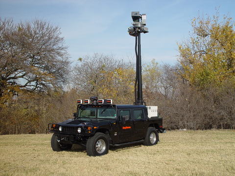
In its current incarnation, the vehicle has thermal sights to allow the user to see in the daytime or at night. The primary sensors on the mast are a long-range Forward Looking Infrared (FLIR) sensor, an Inertial Navigation System (INS) and a Global Positioning System (GPS) receiver. In addition to what's on the mast, there are several Raytheon NightSight infrared sensors attached to the vehicle so that the rest of the crew can look at the immediate area around the vehicle.
The mast is four meters high, and including the height of the vehicle, the sight is over five meters high. The vehicle has a three-member crew: driver, commander and scout/operator. The driver can also use the NightSight sensors to drive in the dark and look around for security purposes. The commander also has controls for the NightSight sensors, operates the connection to the Tactical Internet and directs the other two. The scout/operator uses the Linux crewstation to operate the mast-mounted sensors and their associated embedded systems.
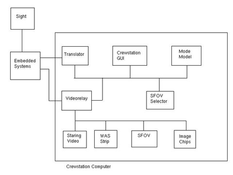
The RSTA-MEP system is mounted onto an H1 Hummer and consists of a mast-mounted sight, embedded computers and a crewstation PC running Linux (Figure 1). These parts connect together as shown in Figure 2.
The embedded computers are digital signal processors that control the mechanics and electronics of the sensor (for example, pointing the sensor or cooling its detector) and some of the image processing. PowerPC boards running VxWorks and single-board computers running Microsoft Windows NT and Sun Solaris also are used. The applications running on these computers include the Force XXI Battle Command Brigade and Below (FBCB2, a US military digital command and control system), target detection and recognition, real-time image processing and communications. The package also includes a GPS receiver, inertial navigation system and digital map functionality. The embedded systems communicate with each other using Ethernet and Virtual Interface protocol (VI) on Fibre Channel.
The prototype Linux crewstation is the successor to an earlier system. The ideal case would have been for our new crewstation to fit in exactly the way the predecessor crewstation had. Our initial attempts to use VI on Fibre Channel failed. Our embedded systems group had considerable experience with vendor compatibility issues, so in selecting Fibre Channel hardware we were limited to vendors who supplied cards and drivers for both VxWorks and Linux. We couldn't find any of those who supported VI protocol. Our second attempt was to try to use disk emulation and imitate a hard drive connected to Fibre Channel, so we could at least stay on the same media.
The results there also were unsatisfactory, so we went to gigabit Ethernet. Ethernet would carry both the video from the sensor and the command and status data between the crewstation and the embedded systems. When looking at gigabit Ethernet, the home audience must consider four things: packet size, media, interconnecting and network interface card. Regular Ethernet has a maximum packet size of 1,500 bytes. An emerging standard for gigabit Ethernet is to allow a 9,000 byte maximum, called jumbo packets. For this project, our concerns about vendor compatibility between the embedded side and the Linux side pushed us to regular packet size.
The second consideration is media. Gigabit Ethernet cards come in two varieties, copper and optical fiber. Although copper is susceptible to electromagnetic interference (EMI), fiber is mechanically delicate. We chose copper because it's cheaper. If EMI became a problem, we always could get an optical card later without changing software. The choice of copper also meant we were compatible with our lab's infrastructure, courtesy of autonegotiation. Our existing network was 10/100 copper.
The third consideration is interconnect. The situation doesn't change too much from 10/100 Ethernet; you have switches, hubs and crossover cables. Switches route traffic so it's seen only by the intended recipient. They handle connections with differing speeds and duplexes, and they have the all-important blinky lights (the status lights on the switch that blink to show activity) to help with debugging. The disadvantages of switches are the cost and that you need a managed switch if you want to use a packet sniffer.
Hubs are the second choice. On the plus side, they are cheaper than switches and have the status lights. On the minus side, we know of no hubs for gigabit Ethernet (only switches), so if you use a 10/100 hub, you sacrifice speed. Hubs also send all packets everywhere, which is good if you're trying to sniff packets but bad if you're trying to limit the amount of traffic on an interface.
Crossover cables are the simplest option. They're the cheapest choice; they require no additional equipment, and you can be sure that no packets are coming from an outside source. On the other hand, there are no blinky lights, no way to connect an outside packet sniffer, and if one interface goes down (common for restarting embedded hardware), so does the other.
We chose switches, although the choice between switches and crossover cables is still a subject of religious debate. We also can pass on a caution about gigabit cabling. Professionally made category 5e or 6 cables are preferable to home-brew cables.
The fourth consideration is your network interface card; they generally come in 32- and 64-bit flavors. The 64-bit cards typically perform better with less draw on your PCI bus' resources. Although we didn't perform a trade study on available products, we chose the Intel Pro/1000 Server Adapter.
We chose to use TCP/IP on Ethernet. Although TCP is slower than UDP, it is a reliable protocol that compensates for any dropped, duplicated or reordered packets. We wanted to get the best-quality video in the face of possible EMI on the vehicle, so we deemed that built-in error correction was essential. Also, because no information is lost, duplicated or delivered out of order, command and status information would be reliable. When coding the socket layer for this, we had to tune the sizes of the socket send and receive buffers (using setsockopt with the SOL_SOCKET SO_RCVBUF and SO_SNDBUF options) to get enough throughput for the video. We also turned off Nagle's algorithm (setsockopt with IPPROTO_TCP and TCP_NODELAY) to reduce the latency between the crewstation and the embedded system, making it more responsive to sensor-pointing commands from the grips attached to the crewstation.
This prototype crewstation comes from Raytheon's Tiger simulator legacy, unlike the embedded side, which is Raytheon's implementation of the US Army's Weapons Systems Technical Architecture Working Group (WSTAWG) Common Operating Environment (COE). Although both the embedded side and the crewstation side are message-passing systems, the two messaging systems are not compatible. A translation module goes between the two. To minimize latency and CPU usage, this translator process is split into two threads using the POSIX threads library. One thread waits for input from the embedded side of a socket and translates it into the shared memory pool used by the crewstation modules. The other thread takes data from the shared memory pool and writes it to the socket for the embedded side to pick up. Dividing this work into two threads and using full compiler optimizations keeps the latency to a minimum.
The video relay module reads a separate gigabit Ethernet network connection devoted to video. It decides in which video window the data is to be displayed and routes it there.
The GUI control panel on the crewstation was generated by Builder's Xcessory (see Resources). Three major concerns drove the design of the GUI: limited screen space, reflecting the state of the embedded side and desire to use a grip instead of a mouse or trackball.
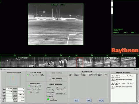
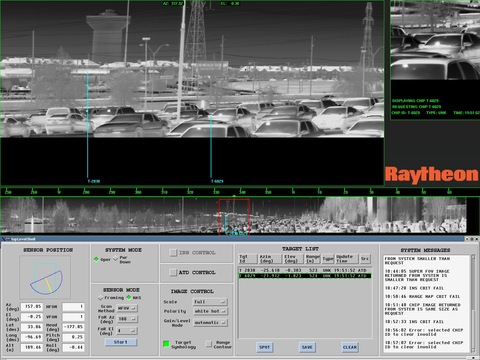
The first major design issue encountered was screen real estate. One monitor was used to display all imagery, leaving only the bottom third of the screen available for the GUI. The mode of the system and the controls for that mode are displayed in this third. The system has two major modes: WAS mode and conventional framing mode. In WAS mode the sensor quickly scans a user-selected area, and the grips allow the user to pick a section of that scanned area to be displayed as a super field of view (SFOV). In framing mode, live video is displayed, and the grips allow the user to point the sensor. As access to framing controls is not needed during WAS and vice versa, both sets of widgets were designed to occupy the same screen space. This is the sensor mode pane of the GUI in Figures 3 and 4. When one set is available for use, the other is hidden. Other functionality, such as controls for the automatic target detection software, was placed in separate windows and made accessible from buttons on the main GUI. These windows pop up over the image display area.
This lack of screen space also presents a second problem. There is a need for immediate visual cues of system response to user input as well as a report of the current state of the embedded side. Rather than use separate widgets for control and status objects, the same widget is used for both. When the operator manipulates a widget, the operator's command is reflected automatically on the GUI, and the widget's callback code is triggered. The callback sends a message containing the requested change to the mode model. This request is passed to the embedded sensor side, which then returns a status. Should the status differ from the request, the mode model notifies the GUI, which in turn updates the widget to display the correct status value.
A third design issue is the need for a mouseless environment. Vehicle movement and lack of physical desktop space make it difficult to use a mouse, trackball or touchscreen. A keyboard is available but is used only for minimal data entry. For these reasons, we desire to manipulate the GUI with the hand grip.
Mouseless mode was accomplished in an early version of the GUI by adding manual widget traversals and button-press events. Moving the hat switch on the grip changed widget focus via XmProcessTraversal calls. Pressing the Select button on the grip defined and sent an XEvent, similar to this:
/* sending key press events */
#include <X11/keysym.h>

XKeyEvent ev;
Window    rootWin;
int       x,y;
int       root_x,root_y;
Window    win;

rootWin =  RootWindowOfScreen (guiScreen);
win = findPointerWindow(rootWin, &x, &y,
                        &root_x, &root_y);

ev.type = (long) KeyPress;
ev.send_event = True;
ev.display = display;
ev.window = win;
ev.root = rootWin;
ev.subwindow = 0;
ev.time = CurrentTime;
ev.x = 1;
ev.y = 1;
ev.x_root = 1;
ev.y_root = 1;
ev.state = 0;
ev.same_screen = True;

ev.keycode = XKeysymToKeycode(display,XK_space);
XSendEvent(display, window, True, KeyPressMask,
           (XEvent *)&ev);
Unlike the current version of the GUI, the previous version consisted of a single topLevelShell that contained only simple widgets, for example, PushButtons and ToggleButtons. The current GUI includes multiple shells (pop-up windows) and composite widgets, such as OptionMenus. Simply calling XmProcessTraversal to change focus does not work across shells. Sending a button press on an OptionMenu pops up the menu choices; however, sending a second button press does not select the option and does not pop down the menu.
The home audience should keep these facts in mind:
The window manager is the boss. When dealing with multiple shells, remember that window managers do not readily relinquish control of the focus—or anything else for that matter.
Widget hierarchy has an effect. The order of traversal in a group of widgets is determined partially by the order in which they were declared in your (or BX's) code.
Be aware of behind-the-scenes code. Consider a RadioBox containing two ToggleButton children, with toggle A selected. When an incoming message to select toggle B is received, simply swapping the values of the children's XmNset resources looks correct on screen. The parent widget, however, still thinks toggle A is selected, which can lead to unexpected Button behavior.
In the current version of our project, a separate process takes input from the hand grip and controls the mouse pointer using a combination of XWarpPointer and the X server's XTest extensions (see Resources). The crewstation also displays video generated from data sent by the embedded side. The video relay process reads this from a socket and dispatches it to a window. There are four windows: framing video, WAS, SFOV and image chips.
As mentioned above, the framing video is live image data. The image in the WAS window is a compressed image strip that represents an image taken by a rapid scan of the sensor across a fixed area. Symbology in the WAS strip includes locations where the targeting systems think there might be targets. The SFOV is a larger view of a user-selected section of the WAS strip that shows more detail. Target symbology and information from the digital map are visible here. Image chips are segments of the scene where the targeting system finds something interesting. These are presented to the operator for evaluation and reporting to other systems that are off-vehicle. Figure 3 shows an outdoor view with the system in framing mode with the GUI, framing video and WAS strip. Figure 4 shows the system in WAS mode with the WAS strip, SFOV, GUI and an image chip window.
Video is implemented in OpenGL as a texture on a polygon, and the data from the video is put into an OpenGL texture and applied to the polygon. Then, when the polygon is drawn you see the image. (See the example code in Listing 1, available at ftp.linuxjournal.com/pub/lj/listings/issue114/6634.tgz, to illustrate the technique.) We chose OpenGL for video because it offers us a lot of options for processing and displaying the data. The image can be resized or rotated if the data is generated on a different orientation from how it's displayed. OpenGL has a lot of primitives for drawing symbology on top of the image, some image-processing ability built-in and double buffering for flicker-free updates. OpenGL is portable and well documented. Additionally, we can off-load a lot of the work from the CPU onto the graphics card hardware.
The SFOV selector controls what part of the WAS strip picture is selected for display on the SFOV window. It also controls where the red rectangle is drawn in the WAS strip window.
The crewstation has a separate control and moding module. Instead of having pieces of logic scattered throughout the modules in the system, they are concentrated in this one module. This design makes the other parts of the system simpler and more reusable. It also makes the moding module fiendishly complex. The mode model has to embody the knowledge of how the other pieces interact and mirror the state of the embedded system and the crewstation. It allows the crewstation to make permissible actions based on that state and monitors the embedded side for errors and unexpected state changes.
The crewstation falls into the category of soft real time: the system doesn't fail if something is late. Because this is a human-in-the-loop test bed, with most of the time-critical components in the embedded systems, it has to run only fast enough for the operator to perform tasks. For this reason we're not using one of the real-time Linux frameworks; we're overpowering the problem with brute-force hardware. We have SCSI disks, enough memory basically to eliminate paging, a GeForce4 graphics card for fast OpenGL and dual 2.4GHz processors from Microway.
A limit did emerge for two parts of the system: video and pointing the sensor. The live framing video is fed to the crewstation at RS-170 rate, one set of scan lines every 1/60 of a second. These had to be combined and displayed fast enough to keep up and maintain a constant rate. To do that, we made sure we had enough network bandwidth to ship the video and plenty of CPU and graphics horsepower to keep the displays refreshed. We then used the NVIDIA driver's ability to sync to the vertical retrace of the monitor. With the monitor set to refresh at 60Hz, we were there. (See the README.txt file supplied with NVIDIA drivers; the current one is at download.nvidia.com/XFree86_40/1.0-4194/README.)
Pointing the sensor presents a similar challenge. The sensor must be responsive enough to the grips that the operator can point it without missing the target and overcompensating. Although the video is largely a matter of bandwidth, pointing the sensor is a matter of latency. Having a long message chain contributes to latency. For instance, a button press or a slewing command starts off in the grip or GUI process, goes to the control process to determine if that input is valid and then moves to the translator to go to EO message format. Next it goes across the gigabit Ethernet to an embedded process that receives that message, then moves to the OE and the embedded systems code, then on to the actuator and, finally, the results come back in the video stream. The combination of dividing the translator process into two threads and compiling with full optimizations (-Wall -ansi -O3 -ffast-math -mpentiumpro) did the trick.
We used the gprof profiler to see where the hot spots were in the code. (See the info page for gprof.) Here, we ran into a problem with profiling the video code: when we used X timers (XtAppAddTimeOut), no timing data accrued in the profile. (Do the profiler and XtAppAddTimeOut use the same signal and interfere with each other?) Another optimization we discovered is for the video source to write both the odd and even scan lines across the network with a single write statement instead of two separate, smaller ones.
Using Linux led to problems in a few places. For instance, we couldn't find a vendor who supplied PCI Mezzanine cards for PowerPC with VxWorks drivers, PCI cards with Linux drivers or who could handle VI protocol. In the end we had to drop Fibre Channel.
We did find, though, a couple of cases where Linux gave us an advantage on this project. Because we booted from a hard drive, we didn't have to write our system to EEPROM the way the embedded side did. When they made that transition to EEPROM, their ability to debug was diminished. Also, Linux provides core files to aid debugging, which VxWorks doesn't. The Linux crewstation is more robust and delivers better image quality than its predecessor. Finally, our shop integration and unit testing are easier on Linux, because commodity PCs are more plentiful than are embedded PowerPCs. In the future, we expect that having the full power and flexibility of the Linux, X and OpenGL environment will be valuable as we add more modes and more devices to our prototype.
Resources
BX is a trademark of Integrated Computer Solutions Inc.: www.ics.com and www.ics.com/products/bxpro
GeForce is a trademark of the NVIDIA Corporation: www.nvidia.com
Microway is a trademark of Microway Inc.: www.microway.com
Power Programming...Motif by Eric F. Johnson and Kevin Reichard, Second Edition Version 1.2, 1993, Management Information Source, Inc. New York, New York. ISBN: 1-55828-319-6.
Raytheon and NightSight are trademarks of the Raytheon Company: www.raytheon.com and www.raytheon.com/products/tiger
Unofficial VxWorks and Tornado FAQ: www.xs4all.nl/~borkhuis/vxworks/vxfaq.html
VxWorks and Tornado are trademarks of Wind River systems: www.windriver.com
VxWorks/Tornado II FAQ (especially section 4.6 on sockets): www.xs4all.nl/~borkhuis/vxworks/vxworks.html
WSTAWG Web Page: wstawg.army.mil/index.asp
XTest Extensions to XFree86: xfree86.org/pub/XFree86/4.2.0/doc/xtestlib.TXT
George Koharchik (g-koharchik@raytheon.com) works for Raytheon's Visualization and Simulation Lab (VSL) and spends his spare time mulling over the mechanics of safety pins.
Quintelle Griggs (Quintelle_Y_Griggs@raytheon.com) works at Raytheon's VSL.
Sonja Gross (sonja_gross@raytheon.com) joined Raytheon's VSL in 2001 after earning her Bachelor's degree in Computer Science from Louisiana Tech University.
Kathy Jones (kajones@raytheon.com) is a software developer at Raytheon's VSL. She develops Motif and VAPS UIs and other software tools.
John Mellby (j-mellby@raytheon.com) works at Raytheon's VSL on virtual simulation architectures, writing short biographies and measuring the Texas sun during the spring equinox.
Joe Osborne (joe.osborne@smiths-aerospace.com) works at Smiths Aerospace in Grand Rapids, Michigan.



346f.png?itok=6_Cm3g2s)

